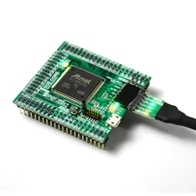
Due Core SAM3X8E 32-bit ARM Cortex-M3 Mini Module Compatible UC-2102 512K Flash 96K RAM 12bit ADC 12bit DAC 84MHz
BUY
Product Description
1. Summary:
- The Arduino Due is a microcontroller board based on the Atmel SAM3X8E ARM Cortex-M3 CPU. It is the first Arduino board based on a 32-bit ARM Cortex-M3 core microcontroller.
- DUE-CORE is a compact version of DUE , It integrates all peripherals required for MCU , and all GPIO are connected to the 2.54mm connectors for users. As a standard MCU core board, apart from main features with DUE also has the following features:
- Compact size: All components are put on a 54 x 58mm 4-Layers PCB. All IO are connected to 116pin 2.54 standard connector. User can apply the PCBA to any application even the size is very compact.
- Easy to use: All IO are connected to 116pin 2.54 standard connector. Only a 5V power to the board to make it work.
- Stable design: adopt high-cost 4-layer PCB layout , two 5V to 3.3V LDO onboard , one is for digital part and one is for analog part. Separate AVCC and AGND, to ensure the best analog performance.
- Easy to set up the development environment: Fully development on Arduino IDE , uploading sketch through standard Arduino 6pin UART interface, standard Micro usb connector , full use of existing resources.
- User-friendly design: Rich LED status indication, two onboard buttons, one is for MCU reset , and other one is for Flase Erase. Unique jumper erase protection against the flash erased by mistake operation.
- Rich resource : All IO are connected out for the user, even if not defined Arduino. Onboard I2C EEPROM designed to compensate for the shortcomings of SAM3X8E no built-in EEPROM.
2. Parameters:
Microcontroller:
|
AT91SAM3X8E LQFP-144
|
Operation Voltage:
|
3.3V
|
Input voltage:
|
5V
|
Total connector pins:
|
44 + 44 + 28 = 116Pins
|
Flash:
|
2 x 256 Kbytes
|
SRAM:
|
64 + 32 Kbytes
|
Clock Speed:
|
84 MHz
|
Number of PIOs:
|
103
|
NAND Flash Controller (NFC):
|
Yes
|
SHDN Pin:
|
Yes
|
EMAC:
|
MII/RMII
|
External Bus Interface:
|
16-bit data / 8 chip selects / 23-bit address
|
Central DMA:
|
6
|
12-bit ADC:
|
16 ch
|
12-bit DAC:
|
2 ch
|
32-bit Timer:
|
9 ch
|
PDC Channels:
|
17
|
USART/UART:
|
3 / 2 (USART3 in UART mode (RXD3 and TXD3 available))
|
SPI:
|
1 SPI controller,4 chip selects +3 USART with SPI mode
|
HSMCI:
|
1 slot, 8 bits
|
Clock Speed:
|
84 MHz
|
Board dimension:
|
54 x 58mm
|
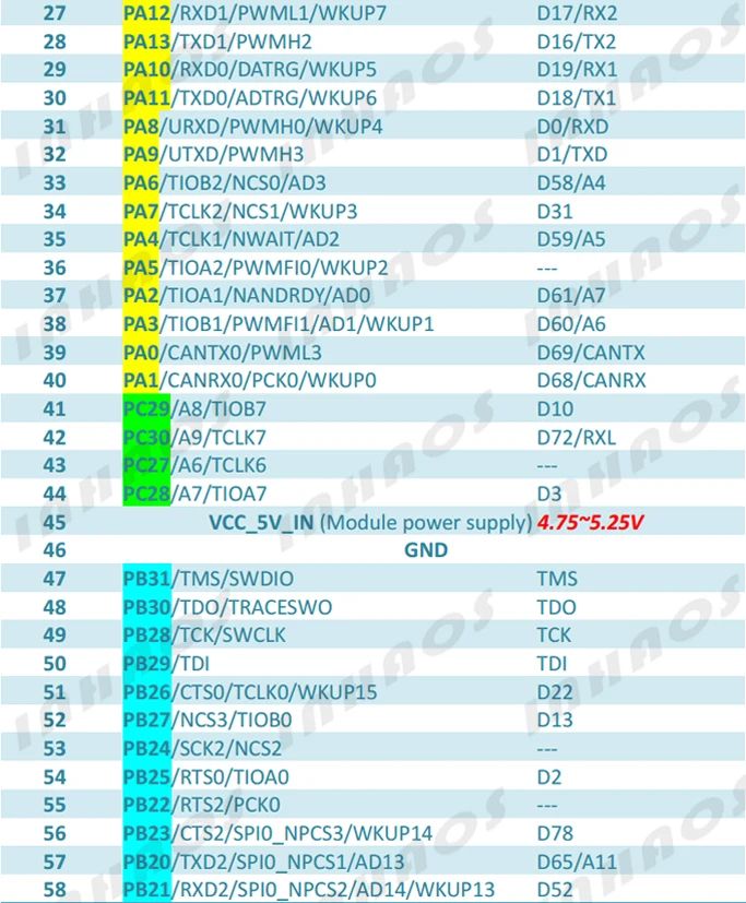
3. Pin Description:


Notes:
- D4 connected to both PA29 andPC26
- D10 connected to both PA28 andPC29
- The board can be powered by Pin45/46 VCC_5V_IN and GND , also can be powered by USB or Programming port.
- If VCC_5V_IN and USB or Programming port are connected at the same time , the board will VCC_5V_IN is priority.
- The VCC_5V_IN must limit tolerance within +/-5% , which means the voltage range is 4.75-5.25V
- The GND(Pin-46) and AGND(Pin-13) are connected by onboard 0R resistor.
4.Typical application
- Power Connection 1: powered by Programming port, in this case , the module can be powered by VBUS_5V form the USB to UART cable (Recommend UC-2102). The connection as below :

- Power Connection 2: powered by VCC_IN_5V, in this case , The VCC_5V_IN must limit tolerance within +/-5% , which means the voltage range is 4.75-5.25V. The connection as below :

- Power Connection 3: Both Programming port and VCC_5V_IN are connected , In this case , the VCC_IN_5V is priority, The connection as below :

NOTE: THE POWER SUPPLY TO THE MODULE IS 5V , BUT THE MCU IS WOKING UNDER 3.3V , THE ONBOARD LDO WILL REGULATE THE 5V POWER TO 3.3V.
5.Uploading Sketch:
The AT91SAM3X8E is already build in bootlaoder , user can be uploading sketch by two ways with Arduino IDE:
- Native port: To use this port, select "Arduino Due (Native USB Port)" as your board in the Arduino IDE. The Native USB port is connected directly to the SAM3X. Connect the Due's Native USB port to your computer. Opening and closing the Native port at 1200bps triggers a 'soft erase' procedure: the flash memory is erased and the board is restarted with the bootloader. If the MCU crashed for some reason it is likely that the soft erase procedure won't work as this procedure happens entirely in software on the SAM3X. Opening and closing the native port at a different baudrate will not reset the SAM3X.
- Programming port: To use this port, select "Arduino Due (Programming Port)" as your board in the Arduino IDE. Connect the Due's programming port to your computer through a standard USB to Serial convertor (UC-2102). The UC-2102 use CP-2102 as a USB-to-serial chip connected to the first UART of the SAM3X (RX0 and TX0). The UC-2102 DTR pin is contorl the Reset pins of the SAM3X. Press the “ERASE button” on the module will triggers a “hard erase” procedure of the SAM3X chip, activating the Erase pins on the SAM3X before communicating with the UART. This is the recommended port for programming the Due. It is more reliable than the "soft erase" that occurs on the Native port, and it should work even if the main MCU has crashed.
- Erase Protection: In order to prevent misoperation to erase Flash data, DUE CORE designed a jumper to connection ERASE buttons and MCU Erase Pin, remove the jumper ERASE buttons and MCU pins can be disconnected, even if this time the ERASE button is pressed, it will not erase Flash data. When your program development is completed, officially delivered to the user in use, remove the jumper, it can be prevent Flash data loss caused by user errors operation.
- Получить ссылку
- X
- Электронная почта
- Другие приложения
- Получить ссылку
- X
- Электронная почта
- Другие приложения

Комментарии
Отправить комментарий